Stage 3: Scan
In the Scan stage, the digital twin of the site is generated from the received raw data traces. This is done by creating mapping rules — via the AI assistant, manually in the rule editor, or by importing a template. A simulation shows the result as a device hierarchy. When the stage is completed, the twin is handed over to the next stage for refinement.
Overview
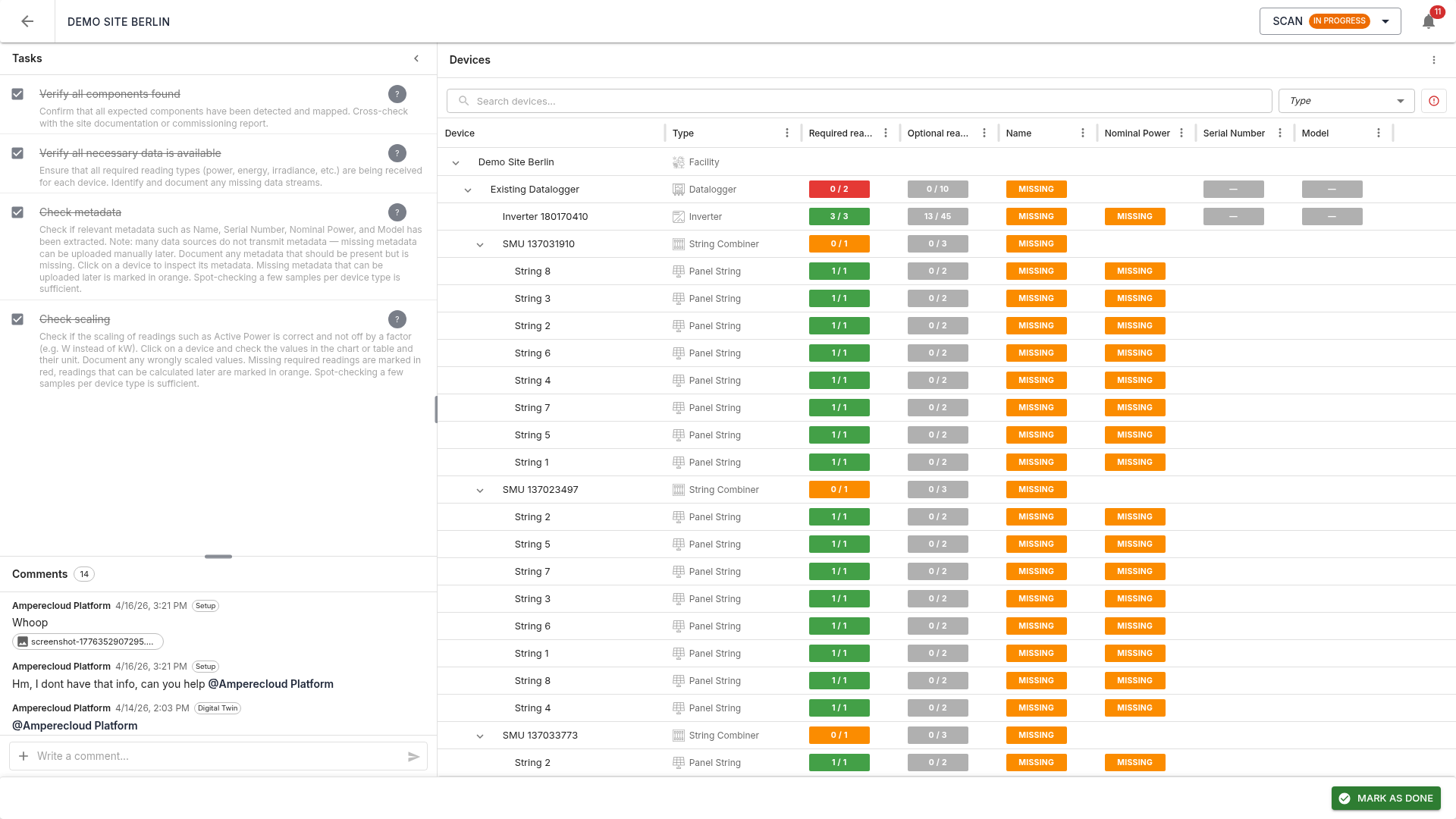
Two-panel layout:
- Left: tasks (4) and comments
- Right: device tree with all detected components of the site
The tree shows the hierarchy: Facility → Datalogger → Inverter → String Combiner → Strings. Each row shows device name, type, metadata (Model, Name, Nominal power, Serial number), and the count of mapped required readings as status pills.
Color coding
- Green: reading / metadata present and mapped
- Red (Required): must be mapped in this stage — otherwise the stage cannot be completed
- Orange (Calculable / Uploadable): needed later, can be calculated or uploaded in a later stage
- Grey (Optional): no action required
Search and filter
The search field and type filter help locate devices quickly — especially useful for large sites.
Side panels
Via the three-dot menu (⋮) in the tree’s toolbar, three panels can be toggled. Only one panel is visible at a time; opening one closes the others. The left sidebar is collapsed automatically to maximize space:
- Show AI assistant — opens the Spark AI chat panel
- Show mapping rules — opens the rule editor
- Show direct mappings — opens the panel for Facility and Datalogger direct mappings
- Reset — discards the current scan state (Amperecloud employees only)
AI assistant (Spark AI)
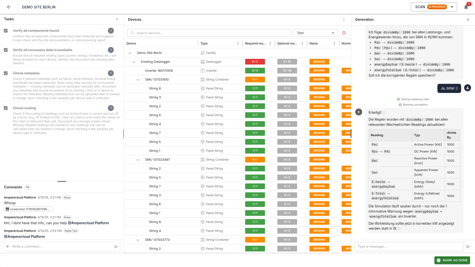
The AI assistant Spark drives the scan process:
- Fetches data sources and the site configuration
- Searches for matching templates
- Analyzes raw traces and metadata
- Creates or adapts mapping rules and saves them per datalogger
- Runs a simulation and verifies the result against the site configuration
The chat shows a summary with device statistics, hierarchy view, and warnings (e.g. unexpected inverter count, missing required readings).
Stop button
A running AI agent can be aborted any time via the Stop button. Cancellation works even from a different browser tab, since status is synced via a server-side event bus.
Mapping rule editor
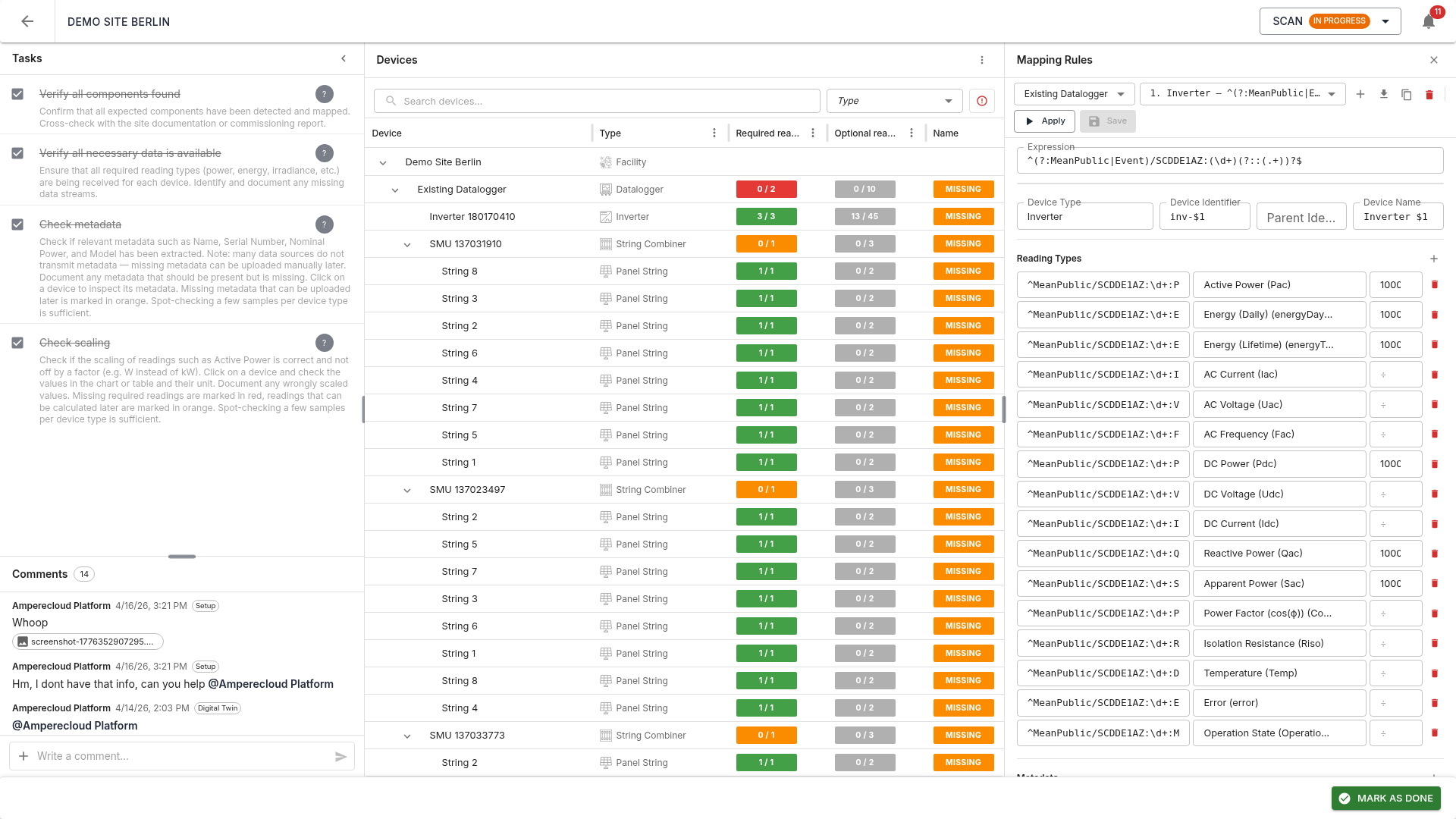
The rule editor lets you create and edit mapping rules manually. Each rule defines how raw traces are mapped onto devices and reading types.
Rule selection
Top of the editor:
- Datalogger selector: which source the rules apply to
- Rule selector: dropdown of all rules, sorted by order
- Add rule: create a new empty rule
- Import from template: import rules from a platform template
- Apply: run a simulation and update the device tree
- Save: save the current rule
Device expression (regex)
The expression defines which raw traces this rule
targets, as a regular expression. Matching traces with their current
values are listed below. Capture groups (parentheses in
the regex) are color-highlighted and can be referenced in the Device ID,
Parent ID, and Device name fields as $1, $2,
etc.
Device configuration
- Device type: (e.g. Inverter, String Combiner, Panel String)
- Device ID: unique identifier (can contain capture-group placeholders)
- Parent ID: ID of the parent device in the hierarchy (empty for root)
- Device name: display name
Reading types
Each row maps a regex to a reading type:
- Expression: regex against the full raw trace name
- Reading type: target reading type on the platform (e.g. Pac, Idc, Udc)
- ÷ (divisor): optional scaling factor (e.g. 1000 for W → kW)
Note: the expression must be unique — it may only match one trace per device. Ambiguous expressions (e.g.
PFmatching bothPFandPFExt) are reported as errors.
Metadata and status codes
Additional sections in the editor let you map metadata (Name, Serial, Nominal power, Model) and Status codes onto the devices.
Direct mappings
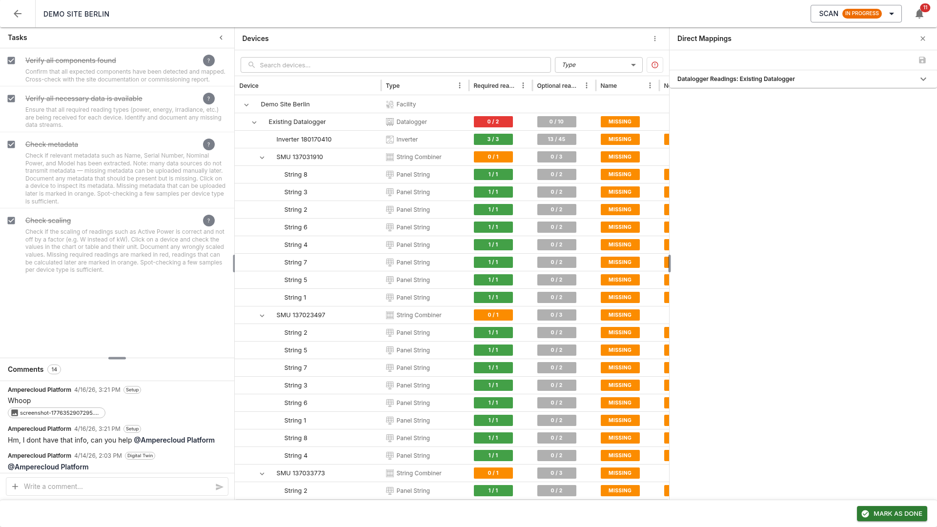
Some required readings do not belong to rule-generated devices but directly to the Facility (the whole site) or a Datalogger. Examples:
- Facility:
energyDelta,energyTotalSum,energyDaySum(at least one required) - Datalogger:
PacLimitRel,gridOperatorActivePowerLimit(at least one datalogger must provide each)
The Direct mappings panel assigns such raw traces directly to an existing device without creating new ones.
Tasks
The Scan stage has four tasks:
- Verify all components found: all expected components must be detected. Cross-check with site documentation or commissioning report.
- Verify all necessary data is available: all required reading types must be received per device.
- Check metadata: Name, Serial, Nominal power, and Model should be extracted as far as available in the raw data. Spot-checks per device type are sufficient.
- Check scaling: values must be plausible and not off by a factor (e.g. W instead of kW).
Tasks 2–4 are only available after task 1 is done.
Complete the stage
Once all tasks are done, complete the stage via “Mark as done”.
Pre-completion validator
Before completion, the system checks:
- No critical errors in the simulation (e.g. invalid metadata expressions, missing required readings)
- No remaining required readings without mapping
If a check fails, an error dialog describes the open issues. The stage can only be completed once everything is resolved.
Note: Completing the Scan stage generates the initial digital twin from the simulation. It is refined in the next stage and only then synced to the platform. If the Scan stage is reopened later, the digital twin is fully rebuilt from the current simulation result on re-completion.
Next stage
Digital Twin unlocks next. → 05-Digital-Twin